Internal Circlip, External Circlip, Flat Spring External Washer, Circlips Screw fix NINGBO YWC IMP. & EXP. CO.,LTD , https://www.nbywc-fastener.com
Application of robot in instrument panel stud welding
Stud welding is a fast and efficient method for attaching fasteners to materials. It not only enhances productivity but also ensures high-quality welds through specialized equipment that achieves full penetration, guaranteeing good thermal and electrical conductivity as well as strong joint strength. When combined with robotic systems, stud welding becomes even more versatile, allowing for welding in all directions. Robotic stud welding offers high precision, consistent quality, and increased speed, making it ideal for modern manufacturing environments.
**Stud Welding Robot Workstation**
A typical stud welding robot workstation consists of seven key components:
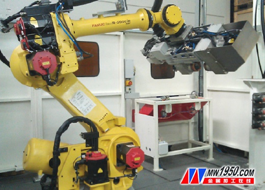
1) A welding robot system: FANUC R-2000iB/165F with an external axis (see photo).
2) Three vibrating hoppers for feeding the studs.
3) Safety and protection systems, including safety light curtains, safety doors, TEKA dust extraction, and compressed air treatment.
4) Three stud welding guns for different applications.
5) A touch screen console featuring a display, suspension arm, operation box, and monitor mounts.
6) Three robot grippers and one set of workpiece loading/unloading fixtures.
7) A PLC control system using SIEMENS S7-300, MP177 color display, three-color indicator lights, station lighting, and a two-hand start button, along with a ProfiBus communication module.
**Workstation Design and Working Principle**
**Design Basis**
1) 2D drawings, product blueprints, and digital models of the dashboard frame.
2) Process standards from the factory.
3) Project bidding requirements.
**Basic Requirements for Welded Parts**
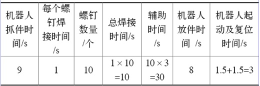
1) The allowable deviation at the weld is less than ±0.5mm. The weld seam and cycle calculation are detailed in the attached table.
2) No flash should interfere with positioning or welding.
3) All parts must match the provided dimensions.
**Working Principle of the Welding Robot Workstation**
After the system starts and all components are ready, the operator places the long and short pipes into the loading fixture at the loading/unloading station. Once assembled, the operator exits and presses the two-hand start button. The fixture automatically clamps the workpiece, the quick shutter closes, and the workstation enters the ready state. The robot returns to its origin, and when conditions are met, it grabs the workpiece and moves it to the welding area. Each gun can weld one screw at a time. The robot automatically selects the appropriate program based on the workpiece type entered on the touch screen.
During welding, the robot’s external axis rotates the workpiece to the optimal angle. The quick shutter opens, allowing the operator to load the next workpiece. After welding, the workpiece is placed on the unloading fixture, and the robot picks up a new one. The process repeats continuously.
The control system uses a SIEMENS PLC S7-300 connected via PROFIBUS-DP to collect signals from the fixtures and send commands to the actuators. The PLC communicates with the touch screen via an MPI cable and with the robot via PROFIBUS. The PLC acts as the master, while the robot is the slave.
The MP177 color display shows the status of each device, and the interface is bilingual (Chinese and English). In automatic mode, the operator simply presses the ready button, and the workstation performs all tasks autonomously. In manual mode, individual steps can be controlled via the touch screen. A three-color tower light indicates the workstation status, and alarms alert the operator to any issues.
The workstation includes service doors and safety locks, and a two-hand start button is located at the loading station. The fixtures use FESTO or DESTACO cylinders, Balluff proximity switches, and solenoid valves for control. The electrical connections use aviation plugs, and the fixture has sensors to detect proper clamping. Interlocks prevent unsafe movements, and the design allows for easy material handling.
The robot gripper is designed to ensure optimal welding posture without interference. The fixture includes 3mm adjustment links for precise positioning, and the surface hardness reaches 40–45 HRC.
**Environmental Requirements**
The workstation requires an ambient temperature between 0°C and 45°C, humidity below 80%, and vibration acceleration less than 0.5g. A three-phase power supply of 380V with a voltage fluctuation range of ±10% and a frequency of 50Hz is needed. The robot control cabinet and welding power supplies must be separated from the main grid. Grounding is essential for the laser generator and control cabinet, with a resistance of less than 100Ω.
Compressed air at 50 N/cm² (filtered) is required, and all equipment must be anchored with expansion Bolts. The floor should have a minimum concrete thickness of 300mm. There are no special requirements for workshop height, doors, or windows.
**Conclusion**
Traditional manual stud welding methods can no longer meet the demands of modern production. Robotic stud welding offers flexibility, precision, and efficiency, making it a technological breakthrough in the industry. By applying robot technology to welding the instrument frame skeleton, manufacturers achieve better welding accuracy and strength, improving overall equipment performance, product quality, and cost efficiency. This advancement significantly boosts the competitiveness of their products in the market.