The general steps are: according to the performance and technical requirements of the parts, several possible heat treatment process schemes are proposed, which are analyzed and compared in terms of performance requirements, process complexity and quality reliability, combined with the size of the production batch and the existing equipment conditions. And the development trend of heat treatment technology at home and abroad, carry out comprehensive technical and economic analysis, and finally determine the best heat treatment process plan. Figure 14-10 is a schematic diagram of the structure of the Dongfanghong 40 tractor drive shaft. The main dimensions are indicated on the map. The drive shaft has a flange at one end and is connected to the rear wheel through a screw hole; the other end is a spline shaft that is connected to the spline hole of the carrier. The drive shaft transmits torque from the planet carrier to the rear wheel through a tight fit of the spline and the taper portion, causing the rear wheel to rotate. Since the weight of the tractor is applied to the rear wheel through the journal and the flange, the drive shaft is also subjected to a bending load. During the operation of the tractor, the rear wheel encounters obstacles, stones, etc., and the drive shaft is also subjected to a certain impact. Once the drive shaft breaks, the tractor will lose support, which will cause overturning, which will affect production, and will cause personal accidents, especially when the drive shaft breaks during mountain transportation. The consequences are even more serious. According to the service conditions of the drive shaft, the design material is 40Cr or 45Cr. The technical requirements for heat treatment are: quenching and tempering, hardness 265~305HBS, no free ferrite in metallographic structure, φ90mm in bearing neck and high frequency quenching in spline part, hardness greater than 53HRC, hardened layer depth not less than 1.5mm, martensite 5 to 6 levels. (1) The process route is: forging → roughing and tempering → processing and forming → φ90mm cylindrical surface and spline two high-frequency quenching. The disadvantage of this process scheme is that the processing allowance is large, the raw materials are wasted, and the quenching and tempering effect is not good. The critical diameter of the steel oil quenching is about 25-33mm, and the diameter of the blank at the transmission torque dangerous section is larger than 55mm (plus the machining allowance). According to the end-quenching curve of the steel, it can be inferred that even the surface is not half. In the Marsh area, only the reticular ferrite and fine-grained pearlite structure can be obtained. The spline-taper junction is just the transition zone (heat-affected zone) of the spline induction hardening, where the strength is worse than that without surface quenching, and it is a dangerous section of stress concentration. The advantages of the process scheme are: overcome the poor quality of the first solution, and the weakness of the high-temperature quenching heat affected zone at the cross section of the taper and spline junction, and the performance of the solution will be greatly improved compared with the first scheme. In the case of constant equipment conditions, the second scheme has a longer production cycle and higher production costs. The flange process route is: forging → quenching and tempering → forming and forming (the spline hole only processes the inner hole, the key groove is not pulled) → φ90mm outer circle high frequency bonfire → broaching spline hole. The advantages of the process scheme are: material saving, in a large number of productions, the spline shaft can order the pipe material from the steel plant; the quenching and tempering effect is good, basically conforms to the critical diameter of the steel; the induction heating quenching process is single and the operation is convenient. The quality is stable, because the purpose of φ90mm external 圃 high-frequency quenching is to improve the wear resistance. The diameter of the joint with the flange is large and the stress is small, so the strength is sufficient. Because it is a through-spline, it can be quenched at one time without a transition zone. Tests show that when the first process scheme is adopted, because the strength is relatively low, when the taper is tightly matched with the planet carrier, shear fracture occurs at the joint between the taper portion and the flange; when the taper portion is not well matched, the torque is not good. When the spline is mainly transmitted by the spline, the shear stress greatly exceeds the shear strength of the material in the transition zone, and the drive shaft will be rapidly sheared and fractured at the spline root, and the life is shorter. It can be estimated that with the third option, the manufacturing cost is not much improved, and the life expectancy is greatly improved, and the overall economic effect is good.
Pyrite Used in Lithium Batteries as Battery Anode Materials
Material for lithium battery cathode
Place of Origin: Henan Luoyang, China
Pyrite, Iron pyrites , pyrites lump, Ferro sulphur, Pyrites powder.
Product Description:
Detailed introduction: it is used as cathode material for lithium battery, which has the advantages of low cost, large capacity, environmental protection and good voltage platform.
The high-grade pyrite is used in lithium batteries as battery anode materials, with benefits of lower cost, large capacity, environmental protection, better voltage platform. Etc.
Quality:
S: 48%min, FE: 42%min, SIO2: 3.0%max, PB: 0.1%max,
ZN: 0.1%max, AS: 0.1%max, . C: 0.3%max, CU: 0.2%max,
H20: 1.0%max, SIZE: 95%min
Granularity: (0-3)mm/(3-8)mm/(3-15)mm/(15-50)mm or other particle size.
Packing: 25KG/500KG/1000KG/BAG or 1000KG/BAG or other packaging.
Note: if there are special requirements, the product can be customized according to clients` requirements.
(In addition, our company is specialized in the production of `Hengkai Metallurgical" Brand - ferro sulphur series for foundry, copper removal agent series for lead smelting, debismuthizing agent for lead smelting, iron sulphide series for resin grinding wheel abrasive industry, iron sulphide series for brake pad friction industry, iron sulphide series for heavy metal wastewater treatment, iron disulphide series for soil improvement, iron disulphide for lithium battery anode, alloy sand series for wear-resisting flooring industry, ferrous sulphide powder series for ferrous sulphide cored wire, ferrous sulphide for ferrous sulphide cored wire, iron sulphide for resin grinding wheel, ferrous sulphide powder for heavy metal wastewater treatment, ferrous sulphide powder for soil improvement, ferrous sulphide cored wire, pyrite, ferrous sulphide ore, molybdenum oxide, high purity molybdenum trioxide, ammonium molybdate, titanium dioxide, cryolite powder, mullite, etc.)
Iron Disulfide For Lithium Iron Sulfide Batteries Iron sulfide battery Lithium battery iron disulfide Pyrite powder Pyrite powder LUOYANG PERFECT TRADING CO.LTD, , https://www.pyritefes.com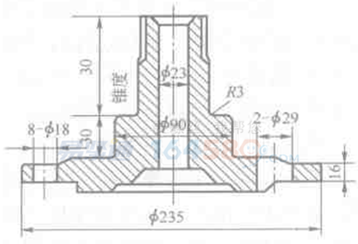
Heat treatment process design steps and methods
As mentioned above, the best heat treatment process plan should first ensure the heat treatment technical requirements of the parts used. On this basis, the quality is required to be stable and reliable, the process is simple, the operation is easy, the management is convenient, the production efficiency is high, and the raw materials are high. Low consumption, low production cost, etc. For a heat treatment process, it is very difficult to fully meet these requirements, and these requirements are sometimes relative. For a part, to achieve the same technical conditions, it can be achieved by different heat treatment process schemes. The requirements should be comprehensively analyzed to select the best heat treatment process plan.
For the determined heat treatment scheme, the laboratory test is first carried out to preliminarily test whether the selected materials and the heat treatment scheme are feasible, and whether the required mechanical performance indexes and other hot and cold processing performances can be achieved. Secondly, on the basis of satisfactory results in laboratory tests, the necessary bench test or loading test is carried out to assess the performance. Third, conduct small batch production tests to assess various process performance and quality stability under production conditions, and further conduct use assessment, and finally production and application. The following is an example discussion.
Figure 14-10 Schematic diagram of the drive shaft structure (dimensions: mm)
According to the technical requirements, the process route and heat treatment scheme can be as follows:
The advantage of the process scheme is that the process is simple, especially the quenching and tempering process, because the mechanical processing is performed after quenching and tempering, and the oxidative decarburization problem does not need to be considered.
(2) The process route is: forging → desert truck and drilling φ23mm hole (should leave machining allowance for reaming into φ23mm)→tempering→machining (including expansion of φ23mm hole)→φ90mm cylindrical surface, taper and spline Partial induction hardening.
The disadvantages of the process scheme are: large processing margin, waste of raw materials; increased processing and inter-process turnover, prolonging the production cycle; strict control of oxidation and decarburization during heating and quenching and tempering; The rounded corner of the taper root R3 needs to be rounded and quenched. In order to avoid the quenching transition zone, the taper and the spline part should be continuously quenched, but the size and geometry of the two parts are different. Therefore, when quenching with the same induction coil, the high frequency quenching needs to be changed. Process parameters (at least the workpiece lifting speed should be changed), the operation is more complicated, and the quality is not stable.
(3) The overall structure is changed into a combined structure, that is, the whole is decomposed into a flange and a spline shaft, the spline shaft is a splined key, and the flange is splined.
The spline shaft process route is: rod drilling → quenching and tempering → forming and forming → spline medium frequency quenching.
The spline is heated by medium frequency, the depth of the hardened layer is increased to 4.5~5mm, and the fatigue strength is improved. After 2500Hz medium frequency quenching and 200°C low temperature tempering, the surface hardness is 53~55HRC. According to the measurement, the root of the tooth has a pressure of 589~736MPa. stress.
A disadvantage of this process solution is the addition of a flange broaching process within the spline hole.
When treated according to the third scheme, the bench test shows that compared with the treatment of the first process scheme, the fatigue life is greatly improved, the conditional fatigue limit torque is increased by 2.8 times, and the ultimate stress amplitude is increased by 4.5 times. . No cracking was observed in the field test for 500 hours.
As for the specific formulation of each heat treatment process, the content should include: selecting equipment and heating methods according to production batch and process requirements, determining each load, heating temperature, holding time, cooling method, cooling medium, and the like. For the chemical heat treatment process, the chemical potential of the furnace gas at various stages of the process, such as carbon potential and nitrogen potential, should be specified.