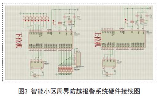
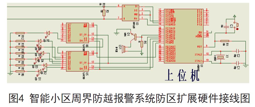
Abstract: With the rapid development of intelligent buildings and intelligent residential communities and the continuous improvement of people's awareness of security, how to establish an efficient and complete security system has become a problem that must be solved. The perimeter anti-over-the-counter alarm system is the core of the intelligent community security system. This paper provides a design scheme of the intelligent community perimeter anti-over-the-counter alarm system based on RS485 bus. It uses the single-chip AT89S52 and MAX485 chip to simulate the front-end alarm information to monitor. The transmission of the center. So that security personnel can deal with the alarm information in a timely manner. 1 Introduction With the rapid development of science and technology and economy, people's concept of home has been from simple accommodation to the humanized demand of housing, such as safe, comfortable, fast and convenient intelligent community, where security is intelligent community design The primary goal. The security system of the intelligent community is responsible for protecting the lives and property of the residents of the community. It consists of subsystems such as perimeter defense, video surveillance, electronic inspection, video intercom, entrance and exit control, and parking lot management. The more alarm subsystem is one of the core of the entire intelligent community security system. 2. Overview of the intelligent community perimeter defense system The intelligent residential community perimeter defense system is designed to prevent people from entering the community from illegal entrances to avoid various potential dangers. In order to prevent the perimeter of the community, prevent the wall or fence from being damaged and illegally overturned, improve the reliability of the surrounding security, shorten the time of discovering illegal intrusion, and ensure the property and personal safety of the residents in the community. Infrared radiation detectors, vibration detectors, and photoelectric detectors are installed around the terrain and detector functions of the community. When someone attempts to illegally cross the perimeter of the cell, the alarm detector will have a signal output, and the monitoring module will transmit the alarm signal to the monitoring host of the monitoring network system of the cell management center, and display the alarm on the electronic map of the monitoring host. The location signal, notify the on-duty personnel to take timely measures to stop the invasion, thus completing the surrounding defense alarm. The main functions of the system include: alarm detector, alarm controller and alarm information processing center. The system structure diagram is shown in Figure 1. 2.1 detector The detector is the eye and nose of the whole system, used to sense the external information, convert it into a level signal, and transmit it to the alarm controller [2]. The detector has a wide variety of functions and functions, which are commonly used in residential alarm systems. The detectors include: infrared radiation detectors, vibration detectors, and photoelectric detectors. The infrared radiation detector uses infrared light to emit a diode through the LED infrared light, and then performs focusing processing through the optical mirror to transmit the light to a long distance, and is accepted by the light receiver. When the light is interrupted, an alarm will be issued; the vibration detector is a detector that detects the vibration of the object and can be alarmed. It can be preset in the wall to issue an alarm when illegal people pass through the wall and dig holes, which can be generated by illegal personnel. The vibration of the detector is composed of a transmitter and a receiver. The light emitted by the transmitter directly enters the receiver. When the illegal person blocks the light before passing through the transmitter and the receiver, the photoelectric switch generates a switching signal. An alarm is issued. When the alarm controller and the detector are usually geographically close, they can be connected by ordinary two-core or four-core wires. 2.2 Alarm Controller The function of the alarm controller is to analyze, judge and process the signals from the detector. First, the controller will collect the switching amount of each input port, convert it to 0, 1 state signal by comparator, and then compare with the initial state to determine whether it is in the alarm state, and send the alarm data to the alarm according to a certain protocol. The information processing center informs the security guards to take emergency measures. 2.3 Alarm Information Processing Center The task of the alarm information processing center is to process the alarm information sent by each alarm controller in the cell. Its main functions include the interpretation of the custom communication protocol, display the alarm detailed information on the electronic map, record the alarm and the alarm situation, and query. Historical alarm information, system information management, etc. According to the alarm information, the community security personnel can quickly obtain information such as the location, type, and surrounding environment of the alarm, and take emergency measures to ensure the personal and property safety of the intelligent community. 2.4 Alarm Information Transmission Protocol The selection of the alarm information transmission protocol is the key to ensure that the alarm information is transmitted in the network as real-time and reliable as possible. The telephone line networking mode has high operating costs and slow networking speed [3]; although TCP/IP alarm networking The method has the advantages of flexible installation, convenience, stability, and high reliability. However, TCP/IP alarms are now used in residential areas, and wireless network access is also used in areas where some households have been decorated and inconveniently routed separately. This kind of network method is susceptible to network viruses, and it is easy to leak alarm signals. Therefore, at present, the domestic bus system is still mostly used. 3. Design ideas The system uses the single chip chip AT89S52 to develop and design an intelligent community perimeter burglar alarm system based on RS485 bus. The single chip of the system is low in cost, and the front end has 32 zones, which can fully meet the needs of a small and medium-sized high-end intelligent community security. The function of the alarm system is the same as that of the XI7400 alarm host currently used on the market. The front-end alarm signal is transmitted to the alarm information processing center through the RS485 bus. The alarm signal transmission rate is fast and is not easily affected by network viruses. The security independence is good; the alarm information processing center alarm information display in the system is realized by analog map, which is more economical and intuitive. Combined with the design norms of the intelligent community perimeter anti-over-the-counter alarm system and the basic principles of security system design, the design ideas are as follows: 3.1 Design of perimeter anti-over-the-counter alarm system based on RS485 bus According to the topographical and regional functional requirements of the perimeter of the community, infrared radiation detection, vibration detector and photoelectric detector are selected. When an alarm signal is transmitted, the address of the defense zone is recognized by the lower computer AT89S52 hanging on the infrared. The lower computer AT89S52 The dial switch is defined as a single zone, a double zone and an eight zone. Then through the front-end transmitter MAX485 conversion module to access the RS485 bus, the signal is connected to the general control room through the RS485 bus, and then receives the signal through the back-end receiver MAX485 conversion module, the signal is transmitted to the upper computer AT89S52, the upper computer AT89S52 receives the signal and judges The address controls the blinking of the LED corresponding to the back end, and the buzzer sounds to remind the management official that the upper computer sequentially drives the simulated map on the defense zone according to the given signal address (the simulated map corresponds to the corresponding defense zone in advance). The administrator can know which zone has an alarm according to the prompt of the light pipe, and can take corresponding measures. After the hardware debugging, as long as the front detector detects the alarm signal, it will trigger the alarm, because the RS485 transmission will not be affected by the network virus, so it is not easy to generate a leak alarm. In addition, the transmission can be achieved by RS485 bus, which can reach 1.2km. The excess distance can also be expanded by adding repeaters, which effectively increases the range involved. Only two transmission lines are conveniently laid on the RS485 bus, and the interference is small after adding the terminating resistor. Therefore, this design study has practicality, advancement and economy. The design scheme is shown in Figure 2. 3.2 backend display extension When the AT89S52 is used as the upper computer, only four interfaces can drive the alarm output such as LED and buzzer, which can realize the alarm display of the 24-channel zone. If there are many alarm points in the cell, the back-end alarm output point will be insufficient, so it needs to be expanded. , we use the use of single-chip and 74HC595 and other chips to achieve its expansion. 3.3 Alarm information processing center Simulation map design and simulation map, the alarm points corresponding to each zone are arranged on the simulation map, and the host computer correspondingly corresponds to the simulated map on the zone according to the given signal address (the simulated map corresponds to the corresponding zone in advance) The driver emits light, and the buzzer will also sound a warning tone to stop the alarm when the manager removes the danger. 4. Specific implementation circuit 4.1 Front-end alarm signal transmission and back-end display circuit The lower computer AT89S52 single-chip microcomputer P1 port is connected to active/passive infrared detection, and the language recognized by the single-chip microcomputer is a high-level language, that is, binary. Therefore, the front-end zone is defined directly based on whether the infrared is started as a binary switch. When the single chip AT89S52 receives the signal from the infrared, the MCU uses the TXD and RXD ports to connect the signal through the DI and RO of the MAX485 chip to the A and B bus of the RS485. The back end also receives the signal through the MAX485 chip A and B. DI and RO are connected to the TXD and RXD of the AT89S52 single-chip microcomputer for communication to realize the identification of the front-end address. The lower computer AT89S52 can be defined as a single zone, a double zone and an eight zone module through the dial switch. The upper machine AT89S52 is used to judge the zone type according to the first two digits, and then judges the zone address through the last six digits. The backend host computer AT89S52 receives When the trigger signal from the front-end zone is reached, the alarm output photodiode and buzzer of the corresponding zone address are controlled. The RET port of the microcontroller received by the back end is connected to the reset circuit. After checking the alarm, the administrator can press the reset button to reset and restart the next round of monitoring. The hardware wiring is shown in Figure 3. 4.2 Backend display circuit expansion The effective transmission distance of the 485 bus mode is 1.2km, and the defense zone can be extended to 24 channels. The general codec can realize the alarm display of the 8-way zone. In order to effectively expand, the MCU is used in this course design and the 74HC595 chip pair is used. It expands, as shown in Figure 4, and can be extended to 128 channels. The 11, 12, and 13 pins of the expansion chip 74HC595 are connected to each other. For expansion, the 9 pins of the previous chip are connected to the 14 pins of the next chip, and can be expanded. 5. Communication mode The system realizes the multi-machine communication mode between the single-chip microcomputers by using the serial port of the single-chip microcomputer. The multi-machine communication system composed of the single-chip microcomputer often adopts the bus-type master-slave structure. In the system composed of multiple single-chip microcomputers, only the upper computer The one-chip computer is the main unit, and the other lower-level machines as the single-zone, double-zone, and eight-zone address modules are all slaves. The multi-machine communication of the single-chip microcomputer needs to complete three parts in the communication process. 5.1 Address Recognition Process In this process, the information sent by the host needs to be accepted by all the slaves. When the serial port mode is set, the slave sends the information to the ninth bit except the slave is set to the multi-machine communication mode, that is, SM2=1. The data must be "1", that is, TB8=1. This is because in the multi-machine communication mode, the slave receives only the ninth data as "1", and the received data is set to be valid. Otherwise, Discard it as invalid data. 5.2 Data Communication Process When the host establishes contact with the slave, the next work is data communication. In order to complete the data transmission well, in general, the host and the slaves that need to communicate at this time must be set to the stand-alone communication mode, and During the entire communication process, both sides of the communication must keep the 9th bit of the transmitted data at 0 to prevent other slaves from accepting data. 5.3 Data communication end process After a certain front-end alarm information is uploaded, that is, after the data communication between the host and the slave ends, the slave will be reset back to the multi-machine communication mode for the next round of monitoring. For example, in this system, the address of the single-zone slave is 51H. When the host calls the machine, data communication starts: the host sends a command, and the slave sends the data to the host after receiving the command. When the data is sent, the slave is restored. Multi-machine communication mode. 6. Conclusion The intelligent community perimeter defense system is an important part of the intelligent community security system. The perfection of the system has also become an important basis for measuring the performance indicators of the intelligent community security system. The author believes that each intelligent community can choose the perimeter defense system implementation scheme according to their respective sizes, comprehensively consider the advancement of technology and reliability and economic feasibility, and choose the solution that suits them. For small and medium-sized high-end intelligent communities. The intelligent community perimeter defense system design provided by this paper not only meets the functional requirements but also meets the economic requirements, which can be used for your reference. (Author: Zhang Chaomin) 

Design of Intelligent Community Perimeter Alarm System Based on RS485 Bus
1 time
Window._bd_share_config = { "common": { "bdSnsKey": {}, "bdText": "", "bdMini": "2", "bdMiniList": false, "bdPic": "", "bdStyle": " 0", "bdSize": "24" }, "share": {}, "image": { "viewList": ["qzone", "tsina", "tqq", "renren", "weixin"], "viewText": "Share to:", "viewSize": "16" }, "selectShare": { "bdContainerClass": null, "bdSelectMiniList": ["qzone", "tsina", "tqq", "renren" , "weixin"] } }; with (document) 0[(getElementsByTagName('head')[0] || body).appendChild(createElement('script')).src = 'http://bdimg.share. Baidu.com/static/api/js/share.js?v=89860593.js?cdnversion=' + ~(-new Date() / 36e5)];